

 English
 中文简体
中文简体Aluminum Windows: The Ultimate Guide to Alloy and Hurricane-Resistant Options
Introduction Aluminum windows have become one of the most popular choices in modern construction, offering a balance of strength, style, and practical...
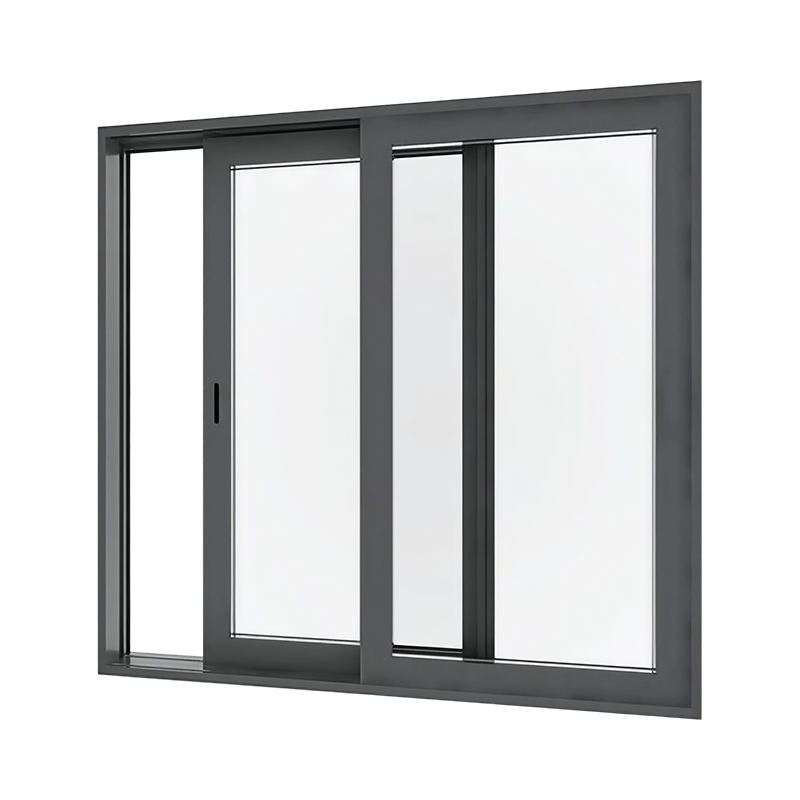
Read MoreThe performance of an aluminum alloy sliding window is determined not by the aluminum itself but by the thermal break that separates the interior and exterior halves of the frame extrusion. An aluminum sliding window without a proper thermal break conducts heat roughly 1,000 times faster than a comparable vinyl or wood frame, but with a 24 mm to 34 mm polyamide strip mechanically crimped into the extrusion, the overall U-factor of the window drops from approximately 7.0 W/m²·K to below 2.0 W/m²·K, bringing it into compliance with energy codes while retaining aluminum's span capability for openings up to 6 meters wide.
Content
The aluminum alloy that forms the frame and sash of a sliding window is almost universally 6063-T5 for residential and light commercial applications, with 6061-T6 specified where the window must withstand higher structural loads such as in high-rise curtain wall integration or hurricane-impact zones. Alloy 6063 contains approximately 0.4% silicon and 0.7% magnesium, a combination that provides an optimal balance of extrudability, surface finish quality after anodizing, and adequate tensile strength. In the T5 temper, cooled from the extrusion press temperature and artificially aged, 6063 achieves a minimum ultimate tensile strength of 150 MPa (21.8 ksi) and a yield strength of 110 MPa (16.0 ksi).
The extrusion process pushes a heated billet of 6063 aluminum at 460°C to 500°C through a steel die whose profile defines the intricate cross-section of the window frame. The die design must accommodate the thermal break channel, the weather-strip grooves, the sliding track rails, and the screw bosses for corner cleats, all within a single extrusion profile. The wall thickness of the extrusion at any point must not be less than 1.5 mm for residential windows and 2.0 mm for architectural-grade systems, as mandated by the Fenestration and Glazing Industry Alliance (FGIA) and the American Architectural Manufacturers Association (AAMA) performance standards. Thinner walls reduce material cost but compromise the screw withdrawal resistance of the corner connections and the long-term resistance to wind-induced cyclic loading.
The thermal break is a strip of low-thermal-conductivity material that is mechanically inserted between the interior and exterior halves of the aluminum extrusion after both halves have been extruded separately. The standard practice, known as the pour-and-debridge method, extrudes the frame as a single profile with a connecting bridge of aluminum, pours a liquid polyurethane or polyamide into the cavity where the bridge is located, allows it to cure, and then machines away the aluminum bridge to create a continuous thermal barrier. The polyamide strip, typically a glass-fiber-reinforced nylon 6,6 with a thermal conductivity of 0.25 W/m·K compared to aluminum's 160 W/m·K, carries the structural shear load between the two halves of the frame while blocking the conductive heat path.
The width of the thermal break is the primary determinant of the frame U-factor. An aluminum sliding window with a 20 mm thermal break achieves a frame U-factor of approximately 2.8 to 3.2 W/m²·K, while a 34 mm break reduces the frame U-factor to 1.6 to 2.0 W/m²·K. The curve of diminishing returns flattens beyond approximately 40 mm; the incremental improvement in U-factor no longer justifies the increased extrusion complexity and the reduction in the glass-to-frame ratio. The choice of thermal break width is therefore a balance between the climate zone requirements of the building energy code and the architectural preference for the narrowest possible sightlines.
The sliding sash of an aluminum window rides on a pair of rollers, typically adjustable stainless steel or polyamide wheels, that run on a raised track extruded into the sill of the frame. The roller assembly is housed in a carrier that clips or screws into the bottom rail of the sash, and an adjustment screw allows the installer to level the sash within the frame and to set the running clearance between the sash and the outer frame to 2.0 mm ± 0.5 mm. A sash that is too low drags on the sill track and causes premature roller wear; a sash that is too high leaves a gap at the interlock between the sliding and the fixed sash that increases air infiltration.
The roller material is selected for the sash weight and the frequency of operation. Nylon-encapsulated ball bearing rollers provide smooth operation with a coefficient of rolling friction below 0.02 and a load rating of 60 kg to 120 kg per pair, sufficient for a residential sash up to 2.4 meters in height. For heavy commercial sashes exceeding 120 kg, stainless steel rollers with sealed cartridge bearings are specified, and the track is reinforced with a stainless steel cap that prevents the aluminum track from galling under the concentrated contact pressure of the roller. The maximum allowable sash weight for an aluminum sliding window is not a function of the extrusion strength alone but of the roller load capacity and the deflection of the sill track under the concentrated wheel load. A sill track deflection exceeding 1/175 of the roller spacing, typically 0.5 mm, causes the sash to rock and bind during operation.
The air infiltration rating of an aluminum sliding window, measured per ASTM E283 at a test pressure of 75 Pa (1.57 psf), is the most direct indicator of the long-term energy performance of the installed window. A window classified under AAMA/WDMA/CSA 101/I.S.2/A440 as an AW (Architectural Window) class product must demonstrate an air infiltration rate of no more than 0.3 L/s per square meter of window area at 75 Pa, a standard that requires a triple-layer weather-stripping system at the interlock between the sliding and fixed sashes.
The weather-stripping materials in a high-performance aluminum sliding window are typically thermoplastic vulcanizate (TPV) or silicone rubber for the compression seals at the sill and head, and a pile weather-strip with a central polymeric fin for the sliding surfaces at the interlock and the jamb. The pile weather-strip, consisting of a woven polypropylene or nylon substrate with a polyethylene vapor barrier fin, must maintain its loft after 100,000 cycles of sash operation without measurable increase in air infiltration. The fin density, measured in fibers per linear centimeter, determines the seal's resistance to air passage; a density of 12 to 16 fibers per centimeter is standard for residential applications, while 18 to 22 fibers per centimeter is specified for high-wind coastal installations where the design pressure exceeds 2,000 Pa.
| Glazing Configuration | U-Factor (W/m²·K) | SHGC | Visible Light Transmittance | Optimal Climate Zone |
|---|---|---|---|---|
| Clear 6mm + 12mm Air + Clear 6mm | 2.7 | 0.70 | 79% | Heating-dominated (Zones 5-8) |
| Low-E (2) + 12mm Argon + Clear 6mm | 1.8 | 0.55 | 72% | Mixed climates (Zones 3-4) |
| Low-E (3) + 12mm Argon + Clear 6mm | 1.7 | 0.27 | 65% | Cooling-dominated (Zones 1-2) |
| Triple 6mm + 2x12mm Argon + 2x Low-E | 1.1 | 0.35 | 60% | Very cold (Zones 6-8) |
The thermal break in an aluminum sliding window addresses conductive heat loss through the frame, but it does not eliminate the risk of condensation forming on the interior frame surface during cold weather. Condensation occurs when the interior surface temperature of the frame falls below the dew point of the interior air, a condition that is most severe at the junction between the glass edge and the aluminum glazing bead. The Condensation Resistance Factor (CRF) of a window, rated on a scale from 1 to 100 per AAMA 1503, must exceed 50 for residential windows in climate zones 4 and below, and must be 60 or higher for zones 5 and above.
The primary defense against condensation is the design of the sill drainage system. The sill of an aluminum sliding window must incorporate weep holes, typically 6 mm x 20 mm slots or 8 mm diameter drilled holes, spaced at no more than 450 mm centers along the outer sill track, with a baffle or cover that prevents wind-driven rain from entering while allowing accumulated water to drain. The sill is sloped toward the exterior at a minimum angle of 5 degrees, creating a positive drainage gradient that empties the sill cavity within two minutes of the cessation of rain. A secondary drainage path, created by the upstand leg of the sill extrusion, serves as a dam that prevents water from overflowing into the interior when the primary weep holes are blocked by debris or ice.
The corners of an aluminum sliding window frame and sash are joined by one of two methods: mechanical crimping using corner cleats, or square-cut butt joints with sealant and screw-fixed corner brackets. The mechanical crimp, or stake joint, is the dominant method for volume-manufactured windows because it is fast, repeatable, and does not require additional fasteners. A hydraulic or pneumatic press drives a hardened steel blade into the corner of the extrusion, displacing the aluminum into a steel corner cleat that has been inserted into the screw bosses of both the horizontal and vertical members. The stake joint must achieve a corner strength of at least 70% of the bending strength of the unjointed extrusion when tested per AAMA 910, a figure verified by a four-point bending test on a representative sample of the frame corner.
For architectural-grade windows with narrow sightlines, the butt-joint method with a hidden corner bracket is preferred because it eliminates the visible stake marks on the interior face of the extrusion. The bracket, typically a zinc die-casting or a machined aluminum block, is screwed into the screw bosses of both members, and a bead of structural silicone is applied to the joint faces before assembly. The silicone, with a tensile adhesion strength of 1.0 MPa (145 psi) minimum to aluminum after primer application, provides the weather seal at the corner, while the bracket carries the structural loads. The corner must pass the same bending strength requirement as the stake joint, but the failure mode is typically fracture of the screw bosses rather than yielding of the corner bracket, indicating that the bracket design is adequately robust.
Aluminum sliding window frames are finished by either anodizing or powder coating, two processes that provide corrosion protection and color but with fundamentally different durability characteristics. Anodizing, per AAMA 611 Class I or II, creates an aluminum oxide layer 18 to 25 microns thick that is integral with the base metal and will not peel or flake. However, anodized aluminum is susceptible to chemical attack from alkaline cleaning solutions, such as those used in masonry cleaning, which etch the oxide layer and create a whitish bloom that cannot be removed without re-anodizing. The color range of anodized aluminum is limited to champagne, bronze, and black tones because the color is created by inorganic metal salts deposited in the anodic pores, not by organic pigments.
Powder coating, applied electrostatically and oven-cured at 180°C to 200°C, produces a film thickness of 60 to 80 microns that is available in any color in the RAL or custom-matched palette. The coating, typically a polyester or super-durable polyester triglycidyl isocyanurate (TGIC) chemistry, must meet the AAMA 2604 standard for high-performance organic coatings, which requires a Florida exposure test of 5 years at 45° south with less than 5 Delta E color change and greater than 50% gloss retention. The powder coating process includes a chromate conversion pre-treatment that passivates the aluminum surface and provides a corrosion-resistant base for the coating film. The scribe creepage at a cross-hatched scribe after 2,000 hours of salt spray testing per ASTM B117 must not exceed 3.2 mm (1/8 inch), a criterion that demonstrates the coating's ability to protect the aluminum from filiform corrosion at cut edges and fastener holes.
The performance of a laboratory-rated aluminum sliding window is meaningless if it is installed into a rough opening with inadequate anchorage and no air seal between the frame and the wall. The window frame is anchored to the rough opening substrate, typically wood studs, steel studs, or concrete, with fasteners at the jambs and the head that are spaced no more than 450 mm (18 inches) on center and no more than 150 mm (6 inches) from any corner. The fastener must penetrate the substrate to a depth of at least 30 mm for wood and 25 mm for concrete, with a minimum pullout resistance of 450 N (100 lbf) per fastener as verified by field testing on a representative sample of the building's rough openings.
The gap between the window frame and the rough opening, typically 10 mm to 15 mm on each side, is filled with a low-expansion polyurethane foam backer rod and sealed with a high-performance elastomeric sealant. The sealant, applied per ASTM C1193 to a minimum depth of 6 mm and a width-to-depth ratio between 1:1 and 2:1, must have a movement capability of at least ±25% as classified by ASTM C920, accommodating the differential thermal expansion between the aluminum frame and the wall without adhesive or cohesive failure. The sealant bead is tooled against the backer rod to create an hourglass profile that maximizes the strain capability of the sealant joint.
On the exterior, a sill pan flashing of pre-formed aluminum, copper, or self-adhering membrane is installed under the window sill and extends up the jambs by a minimum of 150 mm. The sill pan captures any water that penetrates the window's internal drainage system and directs it to the exterior through end dams that prevent water from running off the ends of the pan into the wall cavity. The sill pan is the last line of defense in the water management system; if it is omitted or improperly installed, water damage to the wall structure is inevitable within the first five years of the window's service life, even if the window itself is performing as designed.


