

 English
 中文简体
中文简体Aluminum Windows: The Ultimate Guide to Alloy and Hurricane-Resistant Options
Introduction Aluminum windows have become one of the most popular choices in modern construction, offering a balance of strength, style, and practical...
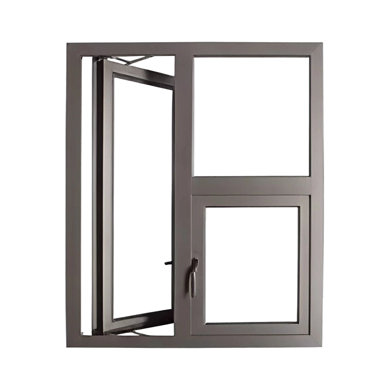
Read MoreA thermal break casement window eliminates the cold bridge that makes traditional aluminum or steel window frames thermally inefficient by separating the interior and exterior metal profiles with a low-conductivity barrier, typically a glass-fiber reinforced polyamide (PA66) strip that is mechanically locked into both frame halves. This barrier reduces the frame's thermal transmittance from approximately 5.5 to 6.5 W/m²·K for a non-broken aluminum frame down to 1.5 to 2.5 W/m²·K for a thermally broken equivalent, a reduction of roughly 60% to 75%. The casement window format—where the sash is hinged at the side and swings outward or inward like a door—provides the best air seal of any operable window type when closed because the compression gasket around the entire sash perimeter is engaged uniformly by the locking mechanism. The combination of a properly designed thermal break and a multi-point locking casement sash creates a window that can achieve a whole-window U-value below 1.0 W/m²·K, meeting the Passive House standard, while retaining the slim sightlines, durability, and large glass area that make aluminum and steel the preferred materials for contemporary architecture.
Content
Aluminum has a thermal conductivity of approximately 160 W/m·K, which is roughly 1000 times higher than wood at 0.12 to 0.18 W/m·K and over 10,000 times higher than rigid polyurethane insulation at 0.022 W/m·K. In an unbroken aluminum window frame, heat flows from the warm interior side to the cold exterior side through a continuous, low-resistance metal path. The interior frame surface temperature drops to within a few degrees of the exterior air temperature, and when that surface temperature falls below the dew point of the interior air, condensation forms on the frame. This condensation not only damages interior finishes but, in cold climates, can freeze on the frame, causing the sash to become stuck and the locking mechanism to jam.
The thermal break interrupts this heat flow path by inserting a material with a thermal conductivity that is three orders of magnitude lower than the aluminum it separates. The heat must now flow from the interior aluminum profile, through the thermal break, and into the exterior aluminum profile. The rate of heat transfer across the thermal break is governed by Fourier's law: Q = (k × A × ΔT) / L, where k is the thermal conductivity of the break material, A is the cross-sectional area of the break, ΔT is the temperature difference across the break, and L is the length of the heat flow path through the break. The polyamide strip is engineered to maximize L—the heat path length—by incorporating multiple internal webs that create a labyrinthine cross-section, and to minimize A—the conductive cross-section—while maintaining the structural strength required to transfer wind loads, sash weight, and operating forces between the two aluminum halves.
The thermal break strip is not a simple rectangular spacer; it is an extruded profile of polyamide 6.6 reinforced with 25% glass fiber by weight, with a complex cross-section that performs multiple functions simultaneously. The glass fiber reinforcement raises the tensile strength of the polyamide from approximately 80 MPa to over 180 MPa and increases its modulus of elasticity from 3 GPa to approximately 8 GPa, giving the composite sufficient structural stiffness to maintain the dimensional accuracy of the window frame under load. The polyamide strip is extruded with longitudinal grooves or serrations on the surfaces that will be embedded in the aluminum profiles, and these grooves provide a mechanical key that, after the rolling or crimping assembly process, creates a positive interlock between the strip and the aluminum.
The assembly of the thermal break into the aluminum frame is a precision manufacturing process. The aluminum frame profile is extruded with a channel on the interior-facing side, and the polyamide strip is inserted into this channel. A rolling machine then passes over the assembly, deforming the aluminum channel walls inward to grip the serrated polyamide strip. The rolling force and the deformation geometry are calibrated to achieve a shear strength of at least 24 N per millimeter of strip length, per the European standard EN 14024, which ensures that the thermal break can transfer the structural loads between the interior and exterior frame halves without slipping or separating. For larger profiles and heavier sashes, a double or triple thermal break may be employed, with two or three parallel polyamide strips creating multiple insulating chambers that increase the thermal resistance and provide redundancy in the structural connection.
| Thermal Break Configuration | Typical Strip Width | Frame Uf Value (Approx.) | Typical Application |
|---|---|---|---|
| Single strip, narrow | 16-20 mm | 2.5-3.5 W/m²·K | Basic thermal improvement, moderate climates |
| Single strip, wide | 24-34 mm | 1.8-2.5 W/m²·K | Residential standard, cold climates |
| Double strip with insulating chamber | 2 x 20-24 mm | 1.3-1.8 W/m²·K | Low-energy and Passive House projects |
| Triple strip with foam-filled chambers | 3 x 18-24 mm | 0.9-1.3 W/m²·K | Passive House certified frames |
The polyamide strip width is the primary geometric parameter that determines the thermal performance of the break. A wider strip increases the length of the heat flow path through the low-conductivity material, reducing the heat transfer per degree of temperature difference. However, a wider strip also reduces the structural stiffness of the composite profile because the polyamide is less stiff than the aluminum it replaces. The profile designer must balance the thermal and structural requirements by selecting the strip width, the glass fiber content, and the internal web geometry. Modern high-performance thermal breaks incorporate low-emissivity foil inserts or aerogel-filled chambers within the polyamide profile to further reduce radiative and convective heat transfer across the break, achieving frame U-values that approach those of solid timber frames.
The casement window format is inherently superior to sliding or double-hung windows in air leakage performance because the sash closes against the frame on a compression gasket, and the locking mechanism can apply mechanical advantage to compress that gasket uniformly around the entire perimeter. A modern multi-point locking casement window uses an espagnolette locking mechanism—a central gearbox operated by a handle, connected to a series of locking rollers or cams distributed along the height of the sash via a concealed drive bar. When the handle is rotated to the closed position, the locking points engage the keepers on the frame and pull the sash tight against the gasket. The number of locking points is determined by the sash height; a sash up to 1200 mm typically requires two locking points, up to 1800 mm requires three, and over 1800 mm may require four or more to maintain uniform gasket compression and to resist the wind loads that try to bow the sash away from the frame.
The air leakage performance of a casement window is measured by the air permeability test per EN 1026, where the window is subjected to a pressure differential of up to 600 Pa and the air flow through the closed window is measured. A window is classified by its air permeability rating per EN 12207, with Class 4 being the highest classification for operable windows, requiring an air leakage rate below 3.0 m³/h·m² at 600 Pa—effectively a negligible leakage that the average occupant will not perceive as a draft. Achieving Class 4 requires not only a multi-point locking system but also a carefully designed gasket system, typically an EPDM (ethylene propylene diene monomer) elastomer with a shore hardness of 55 to 70 Shore A, a compression set below 20% after 24 hours at 70°C, and a temperature resistance from -40°C to 120°C. The gasket is designed with a hollow profile that collapses to a controlled degree when the sash closes, providing a resilient seal that accommodates minor frame movements due to thermal expansion and wind loading without losing contact pressure.
The thermal performance of a casement window is determined by the combined effect of the frame, the glazing, and the edge seal where the glass meets the frame—a zone called the glazing rebate or the spacer area. A thermally broken frame must be paired with a thermally optimized glazing system to realize its full energy performance. The insulating glass unit (IGU) typically comprises two or three panes of low-emissivity coated glass separated by a warm-edge spacer bar and an argon or krypton gas fill. The warm-edge spacer replaces the traditional aluminum spacer with a material of significantly lower thermal conductivity—thermoplastic, silicone foam, or thin-gauge stainless steel with a thermal break—reducing the heat flow at the glass edge where condensation historically appears first. The combination of a double-glazed IGU with a warm-edge spacer, argon fill, and a low-e coating can achieve a center-of-glass U-value of 1.0 to 1.2 W/m²·K; a triple-glazed equivalent can achieve 0.5 to 0.7 W/m²·K.
The glazing rebate must be designed so that the thermal break extends into the glazing zone, preventing the interior aluminum from wrapping around the edge of the glass and creating a thermal bypass. The warm-edge spacer should be positioned within the plane of the thermal break—the principle of "thermal alignment"—so that the isotherms (lines of constant temperature) through the frame and the glass edge are continuous and the coldest point on the interior surface is kept above the dew point. The glass is secured in the rebate by glazing gaskets on the interior and exterior sides, which also serve as the primary weather seal. The exterior gasket is typically a solid profile that sheds water, while the interior gasket is a hollow or co-extruded profile that provides the air seal. The glazing beads that retain the glass must themselves be thermally broken if they are aluminum, or they can be fabricated from a low-conductivity material such as extruded rigid PVC.
The condensation resistance of a window is quantified by the temperature factor (fRsi), defined as the lowest internal surface temperature minus the external air temperature, divided by the internal air temperature minus the external air temperature. A temperature factor of 1.0 indicates that the interior surface is at the same temperature as the interior air; a factor of 0 indicates that the surface is at the exterior air temperature. Building regulations in cold climates typically require a minimum temperature factor of 0.65 to 0.70 at the frame and glazing edge, which corresponds to a surface temperature that remains above the dew point at an interior relative humidity of 50% to 60% and an interior air temperature of 20°C. A non-broken aluminum frame in a climate with an exterior design temperature of -10°C will have a temperature factor below 0.40, guaranteeing condensation and frost formation. A well-designed thermally broken frame can achieve a temperature factor of 0.70 or higher, eliminating surface condensation under normal occupancy conditions.
The condensation risk is calculated using finite element thermal modeling per the methodology of EN ISO 10211, which discretizes the frame and glazing cross-section into a mesh of small elements and solves the steady-state heat conduction equations to map the temperature distribution. The critical node—the point on the interior surface with the lowest temperature—is typically at the junction of the glass and the frame or at the meeting stile where the two sashes of a French casement pair come together. The designer addresses a low temperature factor at these critical points by increasing the width of the thermal break in that zone, by adding an additional insulating element in the glazing rebate, or by relocating the locking hardware to the exterior side of the thermal break so that the metal components do not create a conductive path from the interior to the exterior.
While aluminum dominates the thermal break window market, steel casement windows with a thermal break are specified where minimal sightlines and maximum strength are the overriding design requirements. Steel has a modulus of elasticity of approximately 210 GPa, nearly three times that of aluminum at 70 GPa, which means a steel window frame can achieve the same structural stiffness with a significantly smaller profile cross-section. The sightline—the visible width of the frame and sash when viewed from the interior—can be as narrow as 25 mm to 35 mm for a thermally broken steel casement, compared to 50 mm to 70 mm for an equivalent aluminum window. This slim profile is prized in historic renovations, warehouse conversions, and minimalist contemporary architecture where the window is intended to maximize the glass area and minimize the visible frame.
The thermal break in a steel window is achieved by a different manufacturing process than the polyamide strip used in aluminum. The steel profiles are cut into interior and exterior halves, and a high-density polyurethane resin or a pre-formed composite insulating bar is cast or inserted between them. The assembly is then cured under controlled conditions, creating a structural adhesive bond that joins the two steel halves through the insulating core. The resulting composite profile has a thermal performance that can match or exceed aluminum-polyamide systems, with frame U-values below 1.5 W/m²·K achievable. The corrosion protection of steel—typically a hot-dip galvanized coating followed by a polyester powder coat—must be maintained across the thermal break, which requires careful detailing of the cut edges and the galvanizing process. The premium cost of a steel thermal break window, often two to three times the cost of an equivalent aluminum window, reflects the more complex manufacturing process and the specialized hardware required for the heavier steel sashes.
A thermally broken casement window achieves its design U-value only when it is correctly installed into the building's thermal envelope. The window must be positioned within the wall's insulation layer—not at the exterior face or the interior face of the wall—so that the frame's thermal break is aligned with the wall's insulation plane. This "warm reveal" installation ensures that the isotherms flow continuously from the interior through the wall insulation, through the frame's thermal break, and into the exterior environment, without constrictions that would create cold spots. The gap between the window frame and the rough opening is sealed with a multi-layer system: an exterior weather-resistant, vapor-permeable tape that prevents water ingress while allowing the wall to dry to the outside; a central layer of low-expansion polyurethane foam that provides the primary insulation and air seal; and an interior vapor-tight tape or sealant that prevents warm, moisture-laden interior air from reaching the cold exterior side of the frame and condensing within the wall cavity.
The window's sub-sill and head flashing must be integrated with the wall's drainage plane to direct water that penetrates the exterior cladding away from the window opening. The sill must have a positive slope to the exterior of at least 5 degrees (approximately 1:12 pitch), and the sill pan flashing must extend up the sides of the rough opening and lap over the wall's water-resistive barrier. At the head, a continuous flashing with end dams prevents water that runs down the wall from entering the gap above the window. These installation details are not optional refinements; they are essential for the long-term durability of the window and the surrounding wall assembly, and their omission is the leading cause of premature window failure, even for windows that meet the highest laboratory performance standards.
Specifying a thermal break casement window for a project requires defining the performance requirements and the material and hardware selections in a level of detail that allows accurate tendering and fabrication. The key specification items are:


